
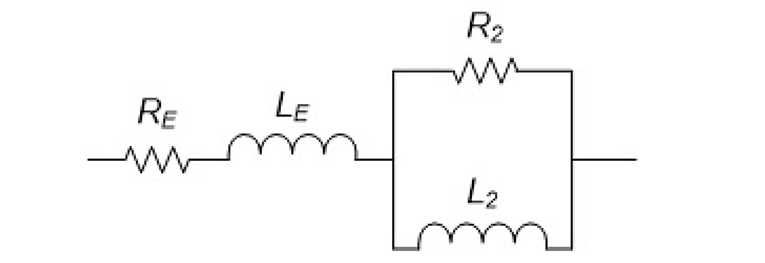
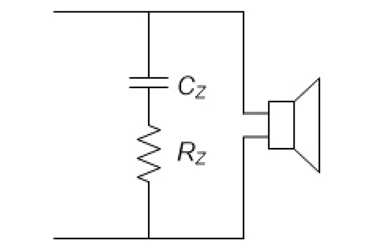
The L2/R2 impedance model [2], [3], depicted in Figure 2 represents the electrical impedance as seen by the amplifier output. The typical Zobel network [4], used to make the driver impedance appear closer to an ideal resistive load above resonance is a simple series resistor and capacitor shunted across the driver terminals (see Figure 3).
The component values are calculated as:
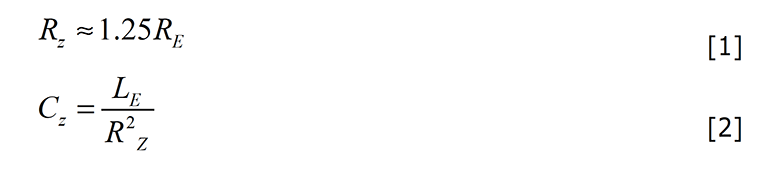
with:
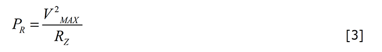
The resistor value is approximate and may need to be adjusted for more extreme voice coil impedances. The resistor should be power rated as shown to handle the current to the loudspeaker. The flatness of the compensated impedance magnitude above resonance is typically limited when using this simplified compensation network.
More complex and accurate compensation networks are possible [5]. An improved compensation network can be realized by using the analogous circuit “dual” of the L2/R2 model, assuming the values for the driver impedance model are known. Recall that a circuit “dual” replaces series impedances with shunt impedances and vice versa. Capacitors become inductors and inductors become capacitors. Resistors remain resistors. Applying these principles to the network of Figure 2 results in the network shown in Figure 4.
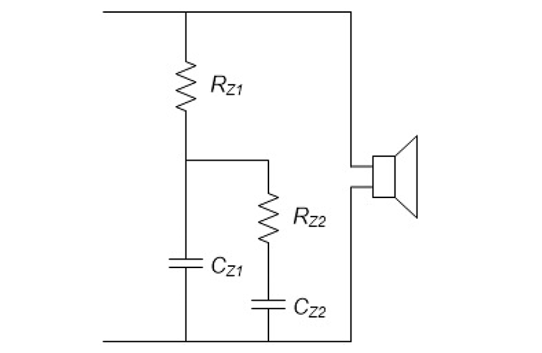
The component values for this improved compensation network are calculated as:
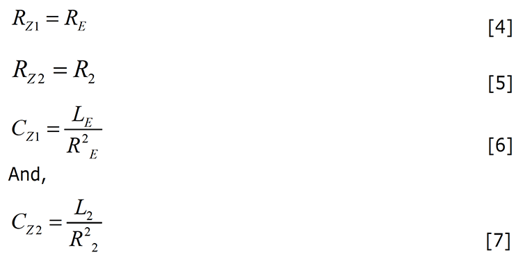
This represents a dramatic improvement to the basic two-component Zobel network and compensates for the non-ideal semi-inductive behavior of the loudspeaker driver across the entire frequency band. The component values are easily found if the L2/R2 impedance model values are known. Again, the resistor values should be power rated to handle the current to the loudspeaker as per Equation 3. Additional circuitry is required to compensate for the motional impedance at resonance.
The cost, however, is increased size, complexity, and component count. VC
Editor’s Note: “Improved Zobel Network” was originally published in CJS Lab Notes, Vol. 12, Issue 4 by CJS Labs.
That article is available at www.cjs-labs.com.
This article was republished in Voice Coil, March 2020.
References
[1] J. Vanderkooy, “A Model of Loudspeaker Driver Impedance Incorporating Eddy
Currents in the Pole Structure,” Journal of the Audio Engineering Society, Volume 37, March 1989.
[2] E. E. Mott and R. C. Miner, “The Ring Armature Telephone Receiver,” Bell System Technical Journal, Vol. 30, (1951) pp. 110-140.
[3] W. Klippel and U. Seidel, “Fast and Accurate Measurement of Linear Transducer Parameters,” presented at the Audio Engineering Society, 110th Conventions, May 2001.
[4] O. J. Zobel, “Theory and Design of Uniform and Composite Electric Wave Filters,” Bell System Technical Journal, Volume 2 (1923), pp. 1–46.
[5] W. M. Leach, “Impedance Compensation Networks for the Lossy Voice-Coil Inductance of Loudspeaker Drivers,” Journal of the Audio Engineering Society, Volume 52, No. 4, April 2004.