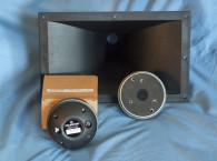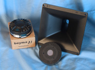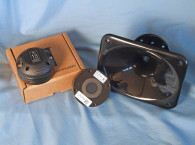
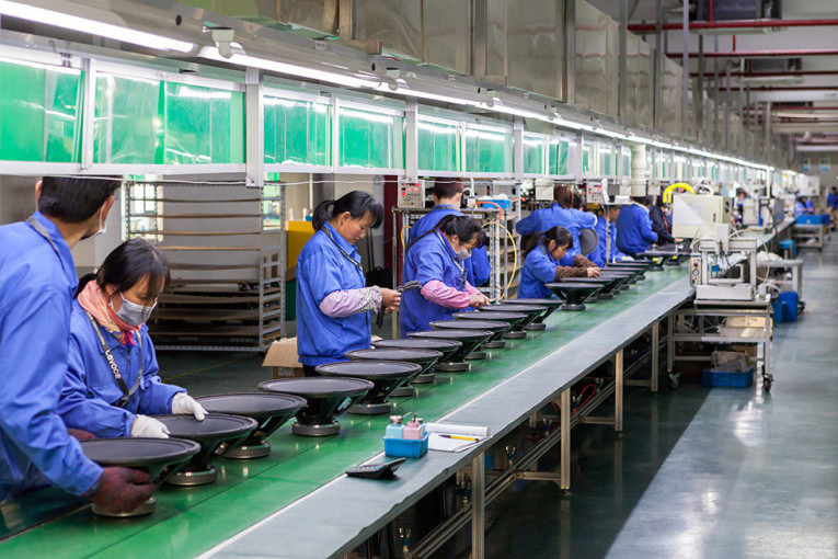
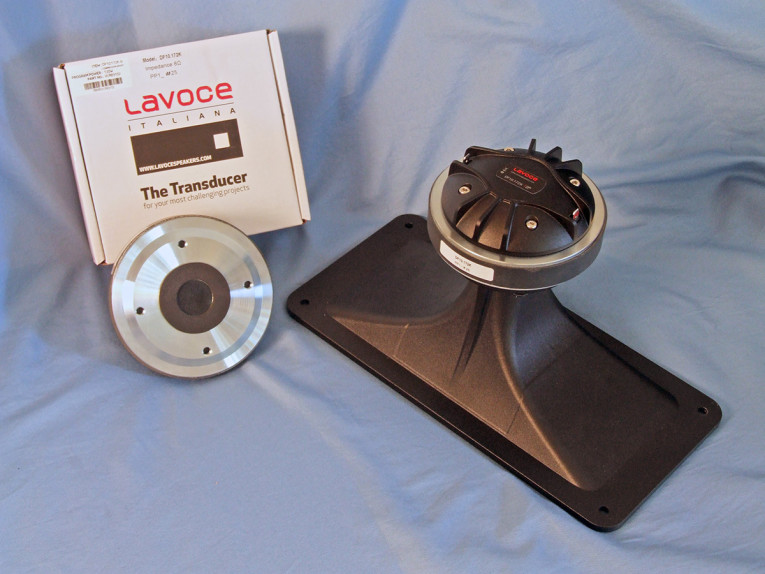
The LaVoce R&D center in Italy has a team of seven electro-acoustic and mechanical engineers, all drawing on a heritage of more than 30 years’ experience of electroacoustic design at the company (see Photo 5). Photo 6 shows the recently released compression driver and horn that LaVoce sent to Voice Coil this month. It is the 1” ferrite magnet DF10.172K combined with the HD1003 cast aluminum 90° × 40° exponential horn (1 kHz cut-off frequency).
Designed for use with 1” throat horns, the DF10.172K has a 25.4mm (1”) throat diameter driven by a 44.4 mm (1.75”) diameter voice coil would with edgewound copperclad aluminum wire (CCAW) on a Kapton former, driving a single-piece polyimide diaphragm and vented polyimide surround.
Other features include a FEA-optimized ferrite magnet motor structure, a phase plug, and a diaphragm with a continuous AES-rated power handling of 60 W with (120 W program material), a 1.6 kHz recommended crossover frequency (12 dB/octave second-order high-pass), and a 2.83 V/1 m 108.5 dB sensitivity measured on the horn.

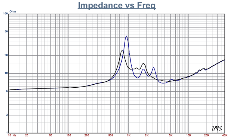
I began testing using the LinearX LMS analyzer to produce the 300-point stepped sine wave impedance plot shown in Figure 1, with the solid black curve representing the DF10.172K mounted on the HD1003 horn and the dashed blue curve representing the compression driver without the horn. With a nominal 8 Ω impedance the DF10.172K had 5.80 Ω DCR (Re), and a minimum impedance mounted on the HD1003 horn of 7.37 Ω and at 4.60 kHz.
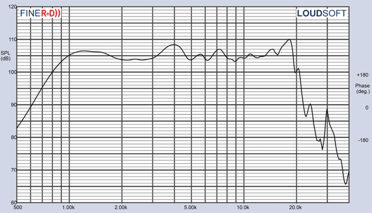
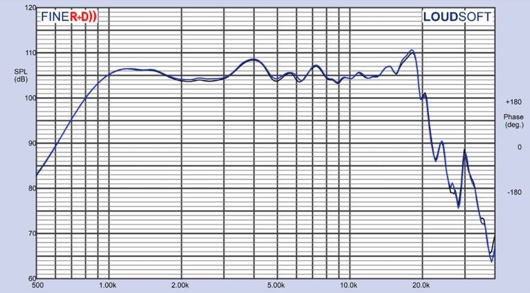
For the next set of SPL measurements, I free-air mounted the DF10.172K/HD1003 combination without an enclosure and measured both the horizontal and vertical on and off axis at 2.0 V/0.5 m (normalized to 2.83 V/1 m) from 0° on-axis to 60° off-axis using the LoudSoft FINE R+D analyzer and GRAS 46BE microphone (supplied courtesy of LoudSoft and GRAS Sound & Vibration). Figure 2 displays the on-axis frequency response of the compression driver/horn, which is a relatively flat ±3 dB with no major anomalies from the 1.6 kHz recommended crossover frequency to about 19 kHz (note this curve has a 1/12 octave smoothing, again, to be in keeping with the 100-point LMS gated sine wave sweeps that I have used for a number of years).
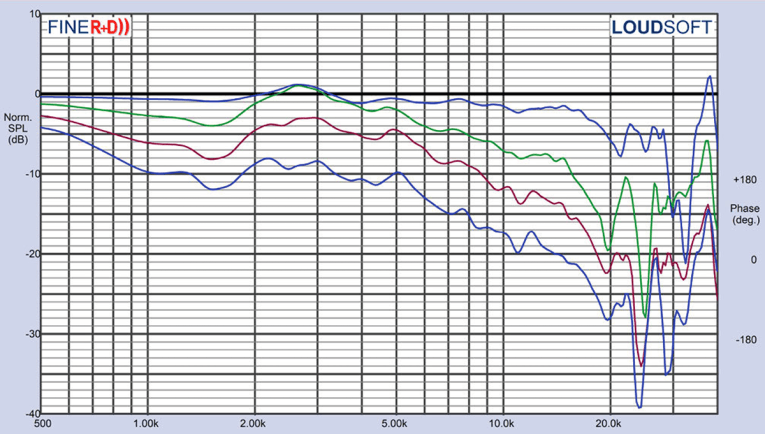
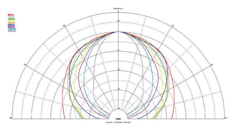

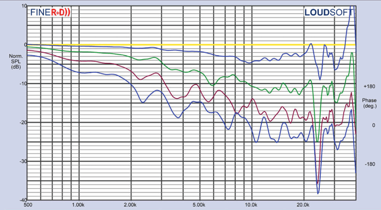
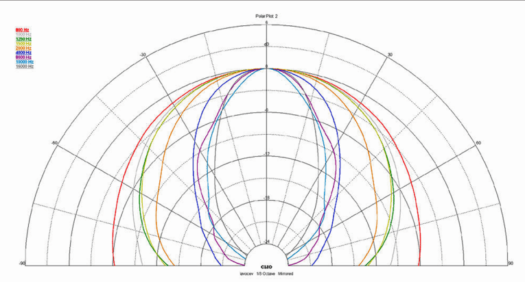
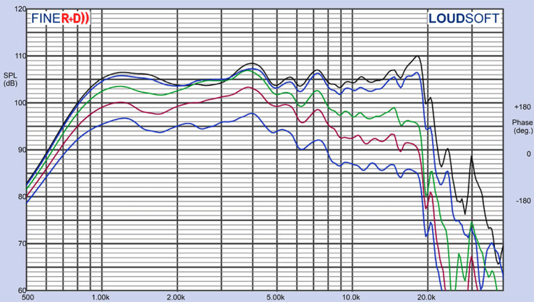
Figure 3 shows the 0° to 60° on- and off-axis response in the horizontal plane. Figure 4 shows the normalized horizontal plane response. Figure 5 displays the 180° horizontal polar plot (in 10° increments with 1/3 octave smoothing applied), generated by the CLIO Pocket analyzer and the accompanying microphone (courtesy of Audiomatica SRL). For the vertical plane of the HD1003 horn, Figure 6 shows the 0° to 60° response, normalized in Figure 7. Figure 8 shows the CLIO-generated polar plot. Last, Figure 9 shows the two-sample SPL comparison showing the two LaVoce DF10.172K compression driver samples to be closely matched within 0.5 dB or less throughout the transducer’s entire operating range.
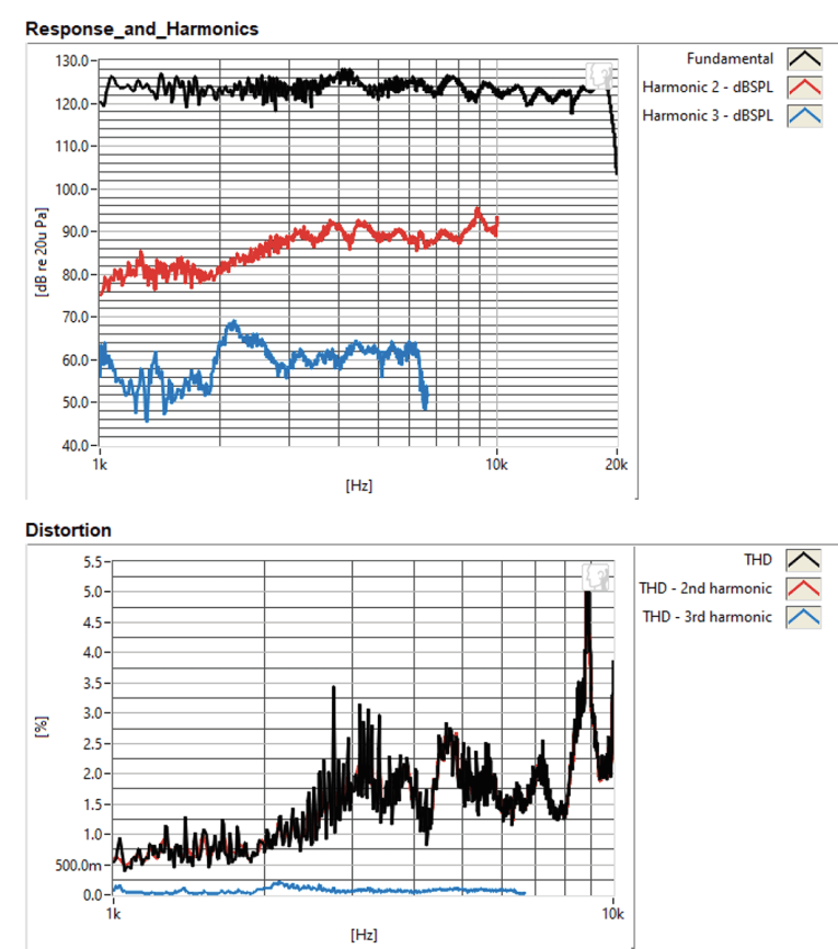
For the remaining series of tests, I set up the Listen, Inc. AudioConnect analyzer and 1/4” SCM microphone (provided by Listen, Inc.) to measure distortion and generate time-frequency plots. For the distortion measurement, the DF10.172K /HD1003H combination was again mounted in free-air in the same manner as was used for the frequency response measurements. I set the SPL to 104 dB at 1 m (2.04 V determined by using a pink noise stimulus generator and internal SLM in the SoundCheck 17 software), and then measured the distortion with the Listen microphone placed 10 cm from the mouth of the horn. This produced the distortion curves shown in Figure 10.
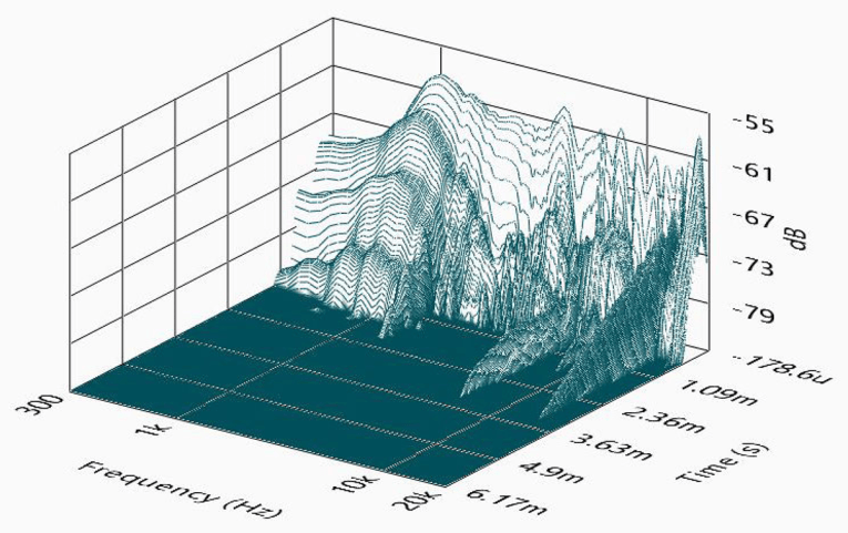
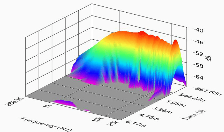
I then set up SoundCheck 17 to generate a 2.83 V/1 m impulse response curve for this driver/horn combination and imported the data into Listen’s SoundMap Time/Frequency software. The resulting cumulative spectral decay (CSD) waterfall plot is given in Figure 11. Figure 12 shows the Short Time Fourier Transform (STFT) plot.
There are a number of really outstanding OEM pro sound transducer manufacturers in Italy…no question about that! I will have to say that with the observable build quality and objective measurement results, LaVoce would seem to fit right in with this group. For more information, visit www.lavocespeakers.com. VC
This article was originally published in Voice Coil, January 2020.