
The more complex new applications and services for webinar and conferencing services, the more difficult testing gets. While in the past a connection in communication systems could always be subdivided in the components near-end terminal, network, and far-end terminal, this separation is not always possible for new types of services. The separation of the components in a connection provides the huge benefit of qualifying each component separately, and ideally guarantees seamless interworking of all components in a connection regardless of which device or network is used. This approach has proven its validity since the beginning of telephony networks. However, it requires the clear definition of interfaces, and it requires the use of a reference interface in testing. The reference interface is part of the test equipment and provides reference access to the device under test (DUT) for certain access technologies.
Due to non-linear time invariant (non-LTI) transmission systems found today (VoIP, VoLTE, etc.), the transmission quality may change even during a call. Therefore, a certain amount of typical network impairments (e.g., jitter and loss) should be included in the device testing of terminals. Another area is the interfacing of components (e.g., headsets or smart speakers), connected wirelessly or via USB. Similar to the tests of terminals, a reference interface is required for testing. For proprietary access technologies in modern conferencing services, a reference interface-based access may not be available.
Different testing and optimization strategies have to be pursued. Here, the focus is on end-to-end quality and testing only at the acoustic interfaces. This article describes the requirements and benefits of reference interface testing as well as end-to-end testing. Using some device examples, important test methods and results are shown.
Reference Interfaces
The definition of interfaces between interconnection points in networks, between terminals and networks, and between user equipment and terminals is key for a successful and seamless transmission of speech. Besides the definition of the electrical or the radio interface, the protocols, and so forth, the definition and knowledge of all communication-relevant parameters is important. When defining a reference interface for testing communication equipment several parameters must be precisely known.
Level
The correct knowledge of reference signal levels is required to adjust and measure levels in sending and receiving correctly. In telecommunication, levels are typically defined in dBm (0 dBm equals to 1 mW typically with 600 Ω termination impedance). In digital systems, dBm0 (represents at the reference frequency (1020 Hz) an absolute power level of L dBm measured at the transmission reference point (0 dBr point), and a level of L+x dBm measured at a point having a relative level of x dBr) is used. Although more easy to understand, the use of dBfs (dB re full scale) is not typical in telecommunication.
Frequency Response Characteristics
The linearity in frequency has to be a magnitude higher than the frequency response characteristics to be measured. This is required for signal generation as well as for signal reception. When the frequency response characteristics are determined by the speech codec used in the transmission system, the accuracy has to be within the limits given by the codec.
Codec Implementation
Ideally, the codec implementation is the reference codec implementation for a given codec. When using reference implementations, any accuracy requirement is fulfilled. If something other than reference implementations are used, the conformance of this implementation to the reference implementation has to be demonstrated.
Clock Accuracy and Clock Adjustment
The clock accuracy of a reference implementation should be high and follow the requirements for the individual interface definition. For measuring clock skew of a DUT, the reference interface should be at least 10 times higher than the clock accuracy of the DUT. For the test of devices with non-synchronized clock and frame interfaces (e.g., VoIP, VoLTE, and Bluetooth), a clock adjustment of the reference interface is required. A clock adjustment enables users to adapt the clock of the reference interface to the clock of the DUT and eliminates the delay drift, which otherwise always occurs during testing.
Delay
The delay introduced by a reference interface must be precisely known. The delay must be stable. With the exception of a procedure for clock adjustment to the DUT, any other adaptive processing (e.g., adaptive jitter buffers), must be deactivated.
Signal Processing and Jitter Buffer Handling
A reference interface shall not include any signal processing other than speech coding and associated filtering for proper band limitation. Signal processing often found in interfaces, such as noise cancellation, echo cancellation, or signal level adjustments, must not be present. As an example, the definition of a VoIP reference interface can be found in the ETSI Guide (EG) [1].
Testing with Reference Interfaces
The most common tests in telecommunication are based on the use of reference interfaces. A typical setup is shown in Figure 1. The tests in such a setup are generally independent of the interface used and consider all perceptual relevant parameters in the talking, listening, and communication situations as well as user behavior and environmental conditions (e.g., room reverberation and background noise). The basics and details can be found in my white paper on the subject [2]. A variety of relevant standards are listed there.
The basic measurements for telecommunication equipment (e.g., Loudness Ratings, response characteristics, distortion, and echo loss) are not considered in the following. These are well known. With the example of some devices, some advanced and important measurements are shown, which cover the user situation and user environmental conditions in a better way.
Delay and Delay Variation — Jitter Buffer Handling
Most systems today work IP-based, and therefore do not work on a synchronized clock. Devices operate on their own clocks and compensate clock deviations from interconnected devices by providing buffers, which may overrun or under-run and discard speech packets from time to time.
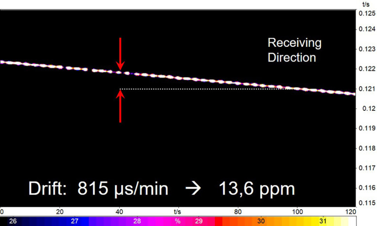
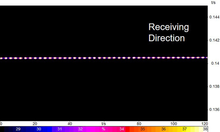
Unsynchronized clocks lead to delay drift between devices, which makes it impossible to determine the delay of a device without special measures. In order to reliably measure the delay of a DUT, the clock of the test equipment needs to be synchronized to the clock of the DUT. This is a function that has to be provided by the reference client. Figure 2 and Figure 3 show the result of clock drift compensation after determining the clock deviation by the reference client.
Besides the handling of any clock drift, the buffer in receiving in IP-based systems serves another purpose — the handling of jitter and packet loss. In non-managed networks, the packet arrival time may change during a call due to time-variant network load resulting in packet jitter.
A de-jitter buffer is used to align the packet stream and allow constant playout of the audio data. The adjustment strategy of the de-jitter buffer is crucial for speech quality. Depending on the amount of jitter, the buffer size needs to be increased in order not to lose too many packets resulting in poor listening speech quality.
Increasing the jitter buffer size too much will result in too high delays and greatly impair the conversational quality [2]. A good compromise has to be found. Therefore, it is advisable to test communication systems under jitter and loss conditions. It is possible to record such conditions in advance and insert those time-synchronous to the audio data [3], [4]. This way different implementations can be tested and optimized under identical conditions.
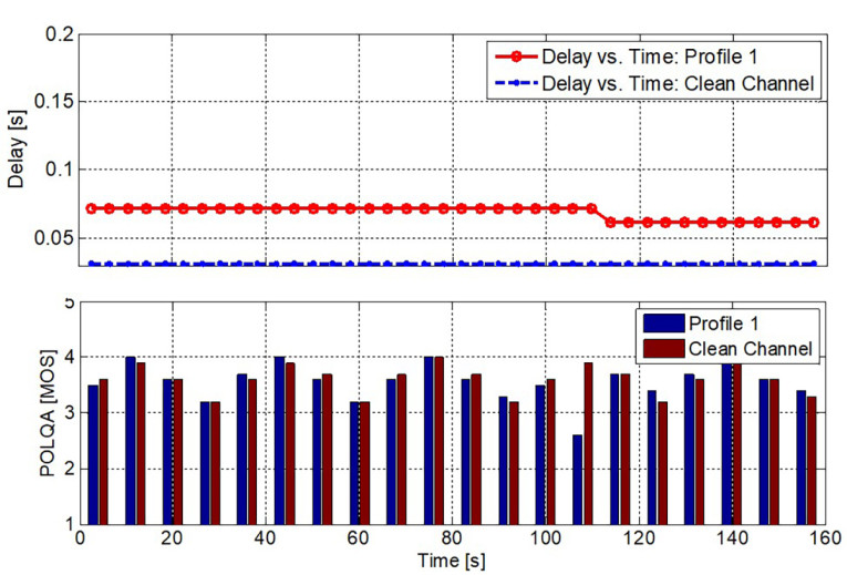
For such a test, a series of sentences lasting typically 160 s pairs (according to Recommendation ITU-T P.501 [5]), are used as a test signal. During the 160 s, two measurements are made. For each sentence pair, the delay is calculated and the Mean Opinion Score (MOS) based on Recommendation ITU-T P.863 [6] are calculated. Both are compared to the clean channel condition. Certain limits (e.g., maximum delay increase and maximum decrease of the MOS value) under clean conditions are evaluated.
A detailed example is given in Figure 4. Jitter obviously increases the delay introduced by the DUT, while speech quality remains almost identical except for one sentence at about 110 s, where a packet loss coincides with a speech sample. Finding the right compromise with low delay keeping good listening speech quality based on a proper packet loss concealment in conjunction with the speech codec used is the art of design.
Echo and Perceptual Echo Evaluation
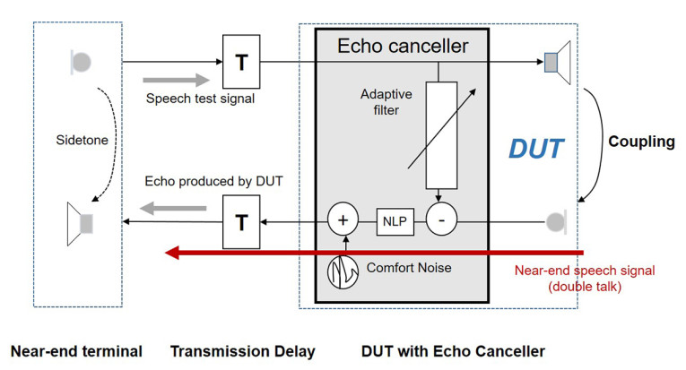
Echo is a very annoying impairment and in contrast to any impairment in the listening situation, it is a talking-related impairment. Echo always originates from the far-end devices, and it is due to the acoustic coupling between loudspeaker and microphone as shown in principle in Figure 5.
Echo tests are well known in telecommunication and the underlying measure is Terminal Coupling Loss (weighted) TCLw [7]. The measurement is simple: A test signal is inserted into the DUT and the loss provided by the terminal and its echo canceller is expressed in decibels (dB) [7].
Typically a requirement of TCLw > 50 dB has to be met in order to provide echo-free connections under all circumstances, regardless of the delay in the transmission system. However, this measurement is perceptionally not correct. The talker and the listener at the near-end terminal perceives the echo more or less masked by her/his own voice. Depending on transmission delay, the echo is more or less audible. With low transmission delays, the echo is not very perceivable, and as a consequence, the loss inserted by the DUT may be less than with high delays. This effect is not covered by traditional tests.
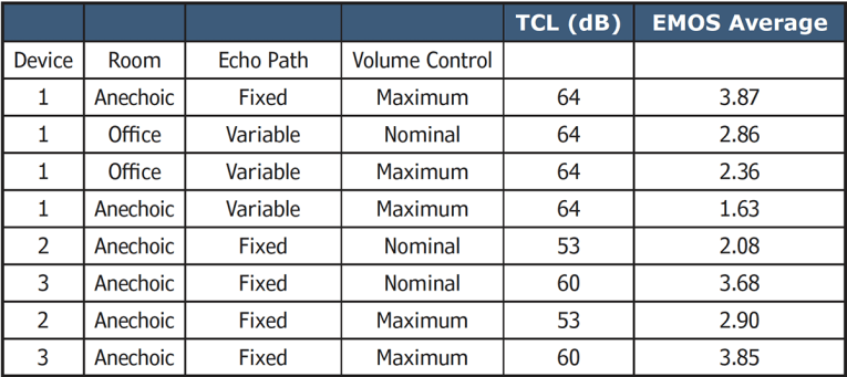
A new procedure developed by HEAD acoustics covers this effect and takes into account the masking effect of the user’s voice. The amount of annoyance caused by the echo is not expressed in decibels but in MOS focusing on the amount of annoyance on a scale from 1-5. 5 represents non-audible echo, while 1 represents a severe echo impairment. This method is called EQUEST. Table 1 provides some results of terminal tests using both methods. Different devices were tested with different settings and for some tests a time-variant echo path simulation was used simulating, for example, user movement in a room.
A rotating plate close to the device, which is exactly controlled by software during the measurement, realizes this time-variant echo path. Furthermore, an office room was used for some tests and the device volume control was adjusted to different positions.
All devices listed in Table 1 would pass the typical TCL requirement of TCL > 50 dB. However, EMOS shows quite different results. Under steady-state conditions, EMOS is > 3.5, which is acceptable echo behavior. However, for some conditions, especially with time varying echo path, EMOS drops drastically. The reason is re-convergence of the echo canceller in the devices leading to short temporal echo peaks. These are just averaged out by TCL, but subjectively these are quite annoying as shown by EMOS. Figure 6 provides a time signal of the echo loss showing these temporal echo peaks.
Conversational Performance — Double-Talk
The performance of devices in double-talk situations (conversational partners talking simultaneously) is a very important performance parameter for conversational quality [2]. A double-talk test requires the simultaneous generation and evaluation of at least two test stimuli inserted from both ends of a communication system or a DUT.
Typically, the main impairments result from the echo canceller in the device. The echo canceller may either not provide sufficient echo cancellation in double talk or the non-linear processor (NLP) required to remove remaining echo may introduce switching impairments.
The near-end speech signal is temporarily cut off. Testing double talk requires synchronized speech test signals. Testing requires the measurement of the DUT delay in order to exactly synchronize the test signal at the DUT, in such a way that the signal overlap in the test sequence is always identical at the DUT. Such test sequences are specified in Recommendation ITU-T P.501 [5] and the appropriate analysis is described in my white paper [2].
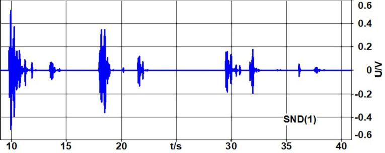
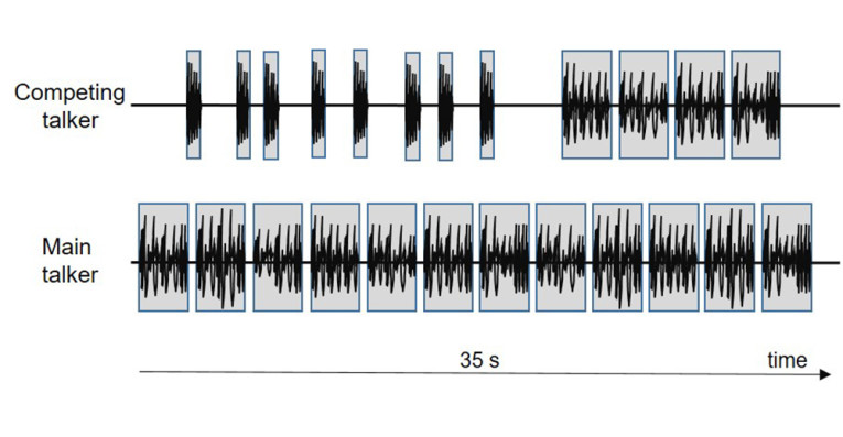
This test is completely independent of the type of DUT. Speech samples (short and long duration) with varying overlapping are inserted from both sides (see Figure 7). The test is basically checking how much attenuation is applied to the various speech segments and calculating a double-talk type [8]. The double talk tests characterization of a device range from 1, 2a, 2b, 2c, to 3 where 1 is a full double-talk implementation, 2a–2c characterize partial double-talk capability, and 3 is a non-duplex device. In a similar way, echo during double talk is evaluated.
If the echo attenuation remains high during double talk, the characterization is a Type 1 device. Less sufficient implementations producing more echo are characterized accordingly from Type 2a to Type 3. The test signal is different, however.
A type of voiced sound, producing a comb-filter spectrum, is created. The signal used in the opposite direction is generated basically the same way but with a different fundamental frequency and harmonics, which do not overlap with the signal inserted in the other transmission direction. The signals are inserted simultaneously from both sides. The separation is made in the frequency domain and this way the amount of echo during double talk can be evaluated.
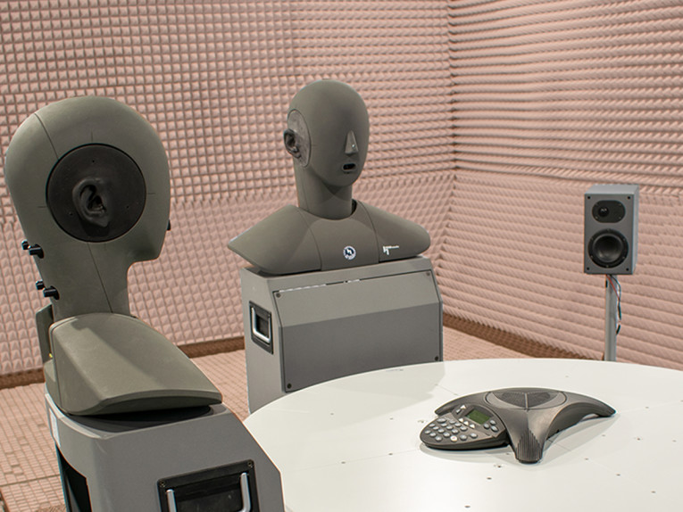
Multi-Talker Testing
A special type of test is the multi-talker test, which is especially important for all types of conference solutions. A multi-talker scenario is simulated by using at least two head-and-torso simulators (HATS), see Figure 1. The focus of such tests is the complete transmission of simultaneous or alternating talkers in a room for all possible talker positions. Some basic tests for this situation are described in Recommendation ITU-T P.340 [9]. One example is the concurrent talker test. The test signal is the same as the one used in the double-talk echo test. Voiced sounds with different fundamental frequencies and non-overlapping comb-filter spectra are produced by the artificial mouths of two HATS (see Figure 8).
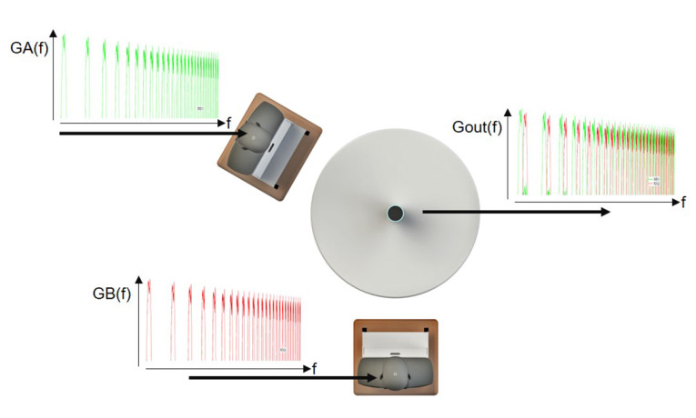
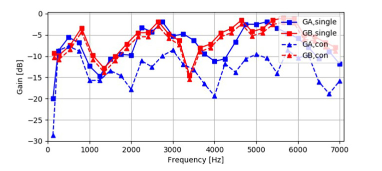
The output signal Gout is analyzed by separating the two signals and determining the frequency dependent gain of each talker separately. When comparing this result to the individual transmission of each signal without concurrent talkers, we can determine the amount of attenuation inserted by the device in case of concurrent talkers. Figure 9 shows a result of this measurement for one device.
For talker A (GA), it can be seen clearly that talker B is attenuated by about 8 dB to 10 dB in the concurrent talk situation, while the gain for talker B (GB) remains almost unchanged. For a conferencing device, this is typically not a preferred behavior.
End-to-End (Acoustic-to-Acoustic) Testing
With no reference client available, virtually only acoustic-to-acoustic tests are possible. Instead of a second artificial head, sometimes a Bluetooth connection or an electrical connection to the second terminal is used. However, since the characteristics of the terminal used for assessing the DUT are unknown, such measurements are only of limited value since it is generally unknown whether effects observed are caused by the DUT or the interface used for connection.
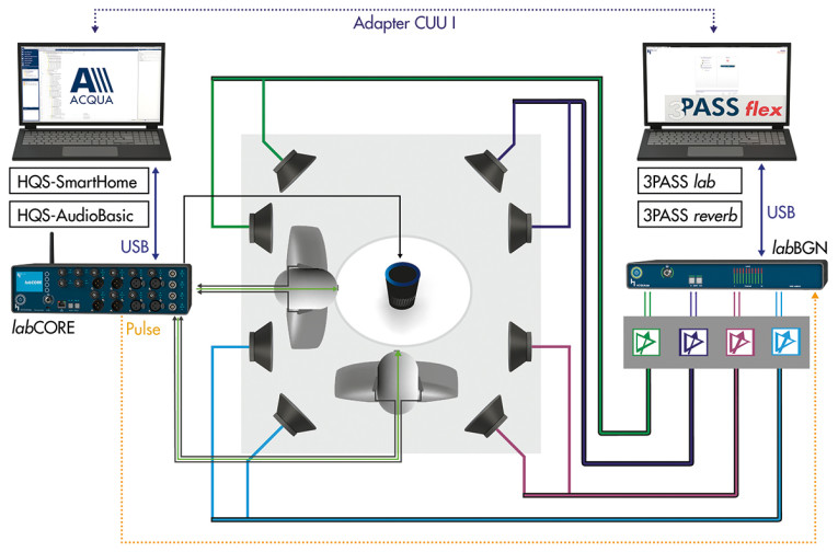
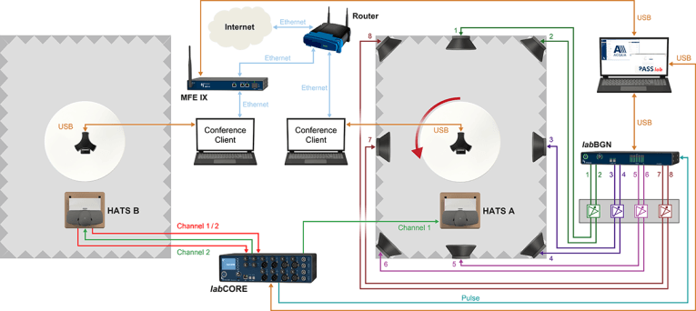
When testing from mouth-to-ear, the same problem is present. However, the benefit of this scenario is that we get the complete user experience of a complete connection. A typical test setup for this scenario is shown in Figure 10.
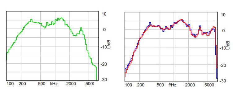
Overall Frequency Response vs. Frequency Response in Sending and Receiving
Although neither sending nor receiving frequency response characteristics can be separated, you get a complete picture of a connection by end-to-end measurements. Moreover, if the connection between the devices is free of artifacts, the result is just the combination sending and receiving response characteristics as shown in Figure 11.
Performing the measurement with different devices can give you an educated guess of the individual sending and receiving characteristics by evaluating different device combinations.
Compensation of Unwanted Signals in End-to-End Testing
Since most of the testing procedures are targeted to the test of one device only, it is required to remove unwanted signals in order to apply traditional testing procedures. This is needed since perceptual based methods are mostly not available for tests where the signals of both conversational partners or the signals in the talking and listening situation are present simultaneously. For such tests, the cancellation of the unwanted signal is required.
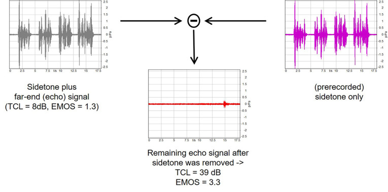
A very elegant procedure about how to perform such cancellation is described in References [10], [11]. The principle is rather simple. You first measure the terminal with the signals not wanted for the analysis. In case of acoustical echo tests, the pure sidetone time signal used is measured and stored using exactly the same test sequence, which is used for the echo test. In a second step, the terminal is activated and the same measurement is performed but now with an activated terminal. In a third step, the prerecorded sidetone signal is subtracted from the measurement performed in Step 2. This requires the exact time synchronization of both signals. The remaining echo signal is then analyzed in Step 4. Figure 12 illustrates this testing with the example of one terminal test.
Without compensation, the signal shown at the left side of Figure 11 is measured. If this would be used (e.g., for TCL calculation) a wrong TCL of 8 dB would be measured. The measurement is completely falsified by the overlaying sidetone signal. If this is removed, the real echo signal (see the middle of Figure 12) is visible and can be used for a reliable analysis of TCL and EMOS.
Conclusions
A large variety of tests and procedures, test arrangements, and simulations of user environments and user behavior is available for optimizing the communication quality of terminals, components, and complete connections from end-to-end. Some important requirements, some test setups, and some test procedures were presented in this article.
Of course, this just covers a fraction of the procedures and setups available. When fully applied, the procedures available are well suited to optimize all types of devices and connections up to the limitations given either by the physical setup of a device or by the technical possibilities built in the individual design.
If applied early in the development process, these procedures and setups enable users to create more superior devices than sometimes found in the market today. In the light of “work from home,“ suppliers might revisit their strategies and focus more on conversational speech quality and less on the costs only. The users will certainly appreciate such solutions. aX
This article was originally published in audioXpress, November 2020.
 About the Author
Hans W. Gierlich started his professional career in 1983 at the Institute for Communication Engineering at RWTH, Aachen. In February 1988, he received a Ph.D. in electrical engineering. In 1989, Gierlich joined HEAD acoustics GmbH in Aachen as vice-president. Since 1999, he has been head of the HEAD acoustics Telecom Division and in 2014, he was appointed to the board of directors. Gierlich is mainly involved in acoustics, speech signal processing and its perceptual effects, QOS and QOE topics, measurement technology, and speech transmission quality. He is active in various standardization bodies such as ITU-T, 3GPP, GCF, IEEE, TIA, CTIA, DKE, and VDA. He is also chairman of the ETSI Technical Committee for “Speech and Multimedia Transmission Quality.”
References
[1] EG 202 425: Speech Processing, Transmission and Quality Aspects (STQ); Definition and implementation of VoIP reference point, The European Telecommunications Standards Institute (ETSI), 2007
[2] H. W. Gierlich, “Communication quality in conferencing scenarios - Principles and optimization potential,” white paper,
www.optimize-audio-conferences.com
[3] ETSI ES 202 737 – ETSI ES 202 740 series: “Speech and multimedia Transmission Quality (STQ); Transmission requirements for narrowband @wideband VoIP terminals (handset, headset & hands-free) from a QoS perspective as perceived by the user,” The European Telecommunications Standards Institute (ETSI), March 2020.
[4] 3GPP TS 26.132, “Universal Mobile Telecommunications System (UMTS); LTE; Speech and video telephony terminal acoustic test specification.”
[5] Recommendation ITU-T P.501, “Test signals for use in telephony and other speech-based applications,” International Telecommunication Union (ITU)-Technical Committee (ITU-T), May 2020.
[6] Recommendation ITU-T P.863, “Perceptual objective listening quality,” International Telecommunication Union (ITU)-Technical Committee (ITU-T), March 2018.
[7] Recommendation ITU-T G.131, “Talker echo and its control,” International Telecommunication Union (ITU)-Technical Committee (ITU-T), November 2003.
[8] Recommendation ITU-T P.502, “Objective test methods for speech communication systems using complex test signals,” International Telecommunication Union (ITU)-Technical Committee (ITU-T), May 2000 and amendments 2010, 2014.
[9] Recommendation ITU-T P.340, “Transmission characteristics and speech quality parameters of hands-free terminals,” International Telecommunication Union (ITU)-Technical Committee (ITU-T), May 2000 and amendments 2014, 2019.
[10] U. Muesch, F. Kettler, S. Bleiholder, “Applications for Time-synchronized Noise Compensation (TNC),“ DAGA Conference Proceedings 2016, Aachen, Germany.
[11] J. Reimes, “Instrumental Assessment of Near-end Speech Quality,” DAGA Conference Proceedings, 2017, Kiel, Germany.